Plant biofeedback
Reading signal from living plant using custom Arduino biosensor
The floral part of the world is fascinating. Some give you yields and some at the first glance are useless but nice to see or smell. For some people, including me, spending time in the nature makes them calm and relaxed. Following recent discussions about feelings and souls of animals, some scientists and philosophers wonder whether we can attribute similar behaviour to plants as well. For the last hundred years, since electronic revolution we try to observe, measure and interpret given electric signals. Thanks to the internet, hobbyists have started their own projects too. And because I have recently got into beginner electronics as well, I decided to make the simplest possible yet functional plant biosensor by tracking voltage signal flowing through the plant.
During my university years, we had an introduction to electronics course. Our lecturer was a nerd invested in his projects. Once he brought a home-made device in which he connected one student at one side and at another person at the other terminal end. His devices measured the electric signal flowing through the person’s body that control muscle contractions and then applied a similar electrical signal to the other person. The final effect of the device was allowing one person to control body of another. This device exploited the fact that our human bodies are basically large, meat mechs controlled by tiny signals starting in our brains. Each move starts decision to send energy to a very precise place in our body. It’s very likely you heard, you should use the back of your hand when touching an unfamiliar electronic device to avoid titanic contraction, so that your hand cannot release the grip and even more current flow through your body, potentially killing or seriously injuring you.
After many years, I decided to check whether someone had done similar project with plants. And because the internet is full of great people sharing their ideas, I found several projects. Some of them were about generating music using the signal flowing through a plant body. Some were interpreting the signal to create nice colour or fractal visualisations. I really liked both ideas. And I decided to try to build my own electronic device so that I could one day connect it to my plants and either listen or see signals of their lives. It’s fascinating that you can connect to anything living, even something as immobile and static as plants, and observe how they react to their surroundings. When you touch the plant, it can react to that. When you cut a leaf, blow on it, or bring a flame near it, it reacts as well. You don’t see this, you don’t hear this but, it reacts.
I started the project by gathering information what I needed to build it. First, I needed the brain of my device. I decided to go for an Arduino Nano. Any other Arduino would be good too, however this one was a bit cheaper than Pro Micro, and I was pretty sure I’ll need a few of them because something might go wrong during the process (it did). Then I needed some way to read the extremely small analogue signal from the plant and amplify to much larger values. A plant usually emits very tiny voltage so we need to amplify it before we can do any digital operations on them. For that, I used AD620. An arduino is a digital device and it operates on digital signals, but whatever I had so far was analogue so I needed converter. The Arduino has built-in ADC (analogue-digital-converter), but it’s only 10-bits. It could work, but I wanted to observer subtle changes as well. I went for ADS1115, a dedicated, precise and low power ADC supporting 16 bit resolution. You can think about resolution in the same as you think about your monitor’s display resolution. It is a measure of how many details you can fit into the whole picture of the state. With six additional bits, you can already represent a great many more state values. Finally, to read the signal I used regular alligator clips with silver needles to (according to the internet) improve the signal-to-noise ratio.
I bought all the items online and waited a few days for delivery. When I got them, it was time to unpack my soldering iron, my old “electronics starter kit” including a breadboard and wires and start working. I read online about schematics of the components and verified using simulators there was a possibility it would work. It could, so I connected the real components using a breadboard as follows:
AD620
Vin - arduino 5v
GND - arduino gnd
S+ red crocodile on plant
S- black crocodile on the soil/trunk
Vout -> to ads1115
V- arduino GND
second GND also to arduino GND

ADS1115
VDD - arduino 5v
GND - arduino gnd
SCL - arduino uno dedicated scl
SDA - arduino uno dedicated sda
ADDR - arduino gnd
ALRT - not connected
A0 - with AD620 Vout
I wrote an absolutely basic program and ran it. I was so impressed that I could read values on the plotter! At that moment I didn’t even know what I had done. So before going further I decided, I needed to learn more about electronics to be more aware of my work.
#include <Wire.h>
#include <Adafruit_ADS1X15.h>

Adafruit_ADS1115 ads;

const uint8_t  ADC_CHANNEL        = 3;
const uint8_t  AVG_SAMPLES        = 16;
const uint16_t CAL_SAMPLES        = 100;
const float    THRESHOLD_MV       = 5.0;
const float    HYSTERESIS_MV      = 1.5;
const float    BASELINE_ALPHA     = 0.005;
const uint32_t TOUCH_TIMEOUT_MS   = 10000;
const uint32_t SAMPLE_INTERVAL_MS = 50;

enum State : uint8_t { CALIBRATING, RUNNING };

State    state       = CALIBRATING;
float    baseline    = 0.0f;
uint16_t calCount    = 0;
double   calAccum    = 0.0;
bool     touched     = false;
uint32_t touchStart  = 0;
uint32_t lastSample  = 0;

float readMV() {
  float sum = 0.0f;
  for (uint8_t i = 0; i < AVG_SAMPLES; i++) {
    sum += ads.readADC_SingleEnded(ADC_CHANNEL) * 0.125f;
  }
  return sum / AVG_SAMPLES;
}

void setup() {
  Serial.begin(115200);
  pinMode(LED_BUILTIN, OUTPUT);

  if (!ads.begin()) {
    Serial.println("ADS1115 not found!");
    while (true) delay(1000);
  }

  ads.setGain(GAIN_ONE);
  ads.setDataRate(RATE_ADS1115_128SPS);
}

void loop() {
  const uint32_t now = millis();
  if (now - lastSample < SAMPLE_INTERVAL_MS) return;
  lastSample = now;

  const float mV = readMV();

  if (state == CALIBRATING) {
    calAccum += mV;
    if (++calCount >= CAL_SAMPLES) {
      baseline = static_cast<float>(calAccum / CAL_SAMPLES);
      state    = RUNNING;
    }
    return;
  }

  const float diff = mV - baseline;
  const float gate = touched ? (THRESHOLD_MV - HYSTERESIS_MV) :  THRESHOLD_MV;

  const bool hit = fabsf(diff) > gate;

  if (hit) {
    if (!touched) {
      touched    = true;
      touchStart = now;
    }

    if (now - touchStart > TOUCH_TIMEOUT_MS) {
      baseline = mV;
      touched  = false;
    }

  } else {
    baseline += BASELINE_ALPHA * (mV - baseline);
    touched   = false;
  }

  digitalWrite(LED_BUILTIN, touched ? HIGH : LOW);

  Serial.print("Upper:");
  Serial.print(THRESHOLD_MV, 2);
  Serial.print("\tSignal:");
  Serial.print(diff, 2);
  Serial.print("\tLower:");
  Serial.println(-THRESHOLD_MV, 2);
}
I started reading more about basics of electricity and electronics to refresh knowledge from university. For that, The Engineering Mindset’s videos were so helpful! The amount of detail in each video was astounding. I wrote several Notion notes what I had learnt. Suddenly many more aspects made sense. While watching the videos I got ideas for many more future projects, but hopefully I will cover them one day. I also had to relearn how to use soldering iron. The last had been so long ago. I had even burnt one while learning back then. I wanted to make sure I wouldn’t do so this time. I found a great video lesson series from PACE WORLDWIDE on YouTube. The whole series covered basic soldering from introduction to materials, through proper usage, to techniques depending on the component you wanted to solder. I even bought several soldering kits to practice and get better at it. While preparing I made my first tiny project of fume extractor using a dense carbon filter and a powerful PC fan connected to 12V and controlled by an external voltage regulator. I even made a wooden case for it to keep everything together like a nice finished device. After a while, I decided I was ready to solder my first PCB for plant biosensor.
I spent two evenings soldering wires back and forth on the two-sided universal blue PCB as precisely as I could. I made a mistake and put all the wires on the same end, even worse on the same side as the components. It turned the whole process into a cluttered hell. I had to be so precise. When I started soldering I hadn’t realised I would need to connect multiple pins to the same wire for 5V or GND. I found tips online about using cut needles across multiple PCB holes. Easier said than done. Anyway after two evenings it was done. Before plugging it into the laptop I read online how to find short circuits using a multimeter. I checked each and every pin and path. Despite looking good I even cut wider gaps in the PCB between the two closest pins and cleaned them with IPA. It looked good so I decided I was ready to plug into my laptop (now I know It would have been better to use powerbank, and even better to flash the Arduino with empty program before!). It worked! I patted myself on the back and smiled widely. I decided, before I recorded video of my device I wanted to polish it a bit. I took a screwdriver and wanted to straighten some pins. That was a bad idea. I accidentally shorted two pins and burnt the device. It went from 100 to zero in one minute after two evenings of soldering. To be honest, I was not even angry or disappointed but rather amused I simply decided to try again.
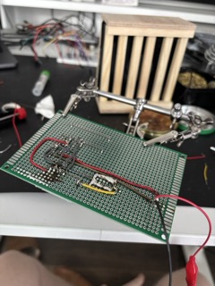
The next approach went much smoother. Before trying again, I completed another soldering kit, read even more and watched other videos with tips and tricks. I bought a different type of solder and flux as well. I tried again. This time I used orange one-sided PCB that was apparently of much lower quality. I didn’t know PCBs can be so drastically different. Whenever I used desoldering pump I destroyed the conductive material around the hole. What a disaster! Despite the problems with the PCB, after around five hours I was done. I finished, tested it and plugged it in again. It worked. But something was odd. After around two minutes of running, the data was not flowing. To this day I don’t know what the reason was. The amplifier? The converter? The microcontroller itself? Once again I decided to try.
Knowing about PCB quality, being much better at soldering than I had been weeks before and having the basics of electronics in mind, I decided to try for the third time. I ordered components again. While waiting for delivery, I was watching, reading and practising again. I talked with my friends in electronics, asking for advice and noting whatever tips they had. When I got the components, the ADC1115 was a bit different from the previous one. It had much larger potentiometers and fewer output pins. The AD620 was also a bit different. It had the same pins but the PCB was a different shape. I read about it online but found nothing. I built breadboard prototype and It worked despite different shapes. So I tried to soldering again. I spent another evening and after around five hours it was done. Once again, I tested and connected it. It worked, but because of the previous problems I was skeptical at first. I kept the device running for the next several minutes. It didn’t crashed but I noticed strange, regular noise. I found that it was ambient electromagnetic noise from the power outlet. I fixed it a bit by applying negative values after reading the unconnected signal for a moment to get the wave duration and peak values. The noise was still there, but much smaller. It was enough to distinguish the plant signal from the power outlet noise. So after a while of tinkering with the software I could finally say it was reading correctly. I just had to regulate amplifier using potentiometers. In the meantime, I wrote a bit better software for reading data. With a working device I went to sleep.
I wrote also simple diagnostic app to check whether basics of my microcontroller works. Nothing special, just baseline to check basic operations and specification.
unsigned long iteration = 0;

void setup() {
  Serial.begin(9600);
  pinMode(LED_BUILTIN, OUTPUT);

  delay(1000);
  Serial.println("\n=============================================");
  Serial.println("    ARDUINO NANO STRESS TEST INITIALIZED     ");
  Serial.println("=============================================");
  Serial.println("Running continuous heavy workload loops...");
  Serial.println("If the board crashes or resets, 'Iteration' will drop to 1.\n");
}

void loop() {
  iteration++;

  Serial.print("[RUN #");
  Serial.print(iteration);
  Serial.print("] ");

  unsigned long startTime = millis();

  volatile float mathTrigStress = 0.0;
  for (int i = 0; i < 3000; i++) {
    mathTrigStress += sin(i) * cos(i) + sqrt(i);
  }

  const int bufferSize = 200;
  byte memoryBuffer[bufferSize];

  for (int i = 0; i < bufferSize; i++) {
    memoryBuffer[i] = (i % 2 == 0) ? 0xAA : 0x55;
    memoryBuffer[i] ^= (byte)i;
  }

  unsigned int ramChecksum = 0;
  for (int i = 0; i < bufferSize; i++) {
    ramChecksum += memoryBuffer[i];
  }

  for (int j = 0; j < 100; j++) {
    digitalWrite(LED_BUILTIN, HIGH);
    delayMicroseconds(50);
    digitalWrite(LED_BUILTIN, LOW);
    delayMicroseconds(50);
  }

  unsigned long totalTime = millis() - startTime;

  Serial.print("CPU: OK | RAM Checksum: ");
  Serial.print(ramChecksum);
  Serial.print(" | Compute Time: ");
  Serial.print(totalTime);
  Serial.println(" ms");
}
The next day I thought what my idea for the observed signal was? Audio? Video? An abstract project? A more practical one? I decided to postpone the decision for another day. In the meantime I had another idea. I wanted to make it look like a complete product. Non-commercial but end-to-end product. I really like finishing projects. I got so much satisfaction for finishing projects. At that moment I decided I needed a case. I looked in nearby stores for small plastic boxes where I could put the device inside to protect it from water it was placed near the plant. But that was not enough. I wanted to make an entire plant pot with a built-in plant biosensor.
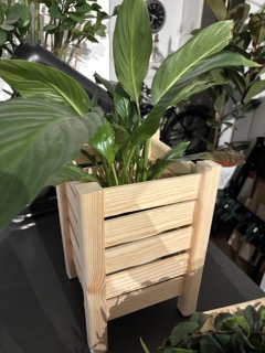
To do that I scrolled through several Pinterest walls. I read a bit more about DIY woodworking and decided to give it a try. I had a jigsaw, a drill and a router. I bought some planed pine boards and square timbers. I cut them to make legs and sides, and used D2 wood glue to join them. I put them in clamps and waited around half a day per side to let them dry fully. After three days I had all the sides done including the bottom. It looked nice. However I wanted to make it smaller, more regular and using wooden screws instead of glue. I tried again in a similar manner, only that instead of glue I drilled a tiny holes and connected the joints in different way. This second approach was much denser. I put some of my plants inside both planters and it looked so good in both! I gave one of the planters away and kept the other one to finish my project. At this stage I only needed to decide on the representation of the data and the final evaluation.
First, I decided to try how my plants sounds like. I gathered signal and wrote a tiny script that assigned music notes to signal value based on initial baseline. That’s software approach to get generative music like Shane Mendonsa does using his devices with eurorack hardware. I gathered values from serial to CSV file having a cap of 1GB just in case something goes wrong using this tiny script:
import csv
import io
from datetime import datetime

import serial

SERIAL_PORT = "/dev/cu.usbserial-210"
BAUD_RATE = 115200
MAX_FILE_BYTES = 1_000_000_000

OUTPUT_FILE = (
    f"sensor_log_{datetime.now().strftime('%Y%m%d_%H%M%S')}.csv"
)


def encode_csv_row(*values):
    buffer = io.StringIO(newline="")
    writer = csv.writer(buffer, lineterminator="\n")
    writer.writerow(values)
    return buffer.getvalue().encode("utf-8")


print(f"Connecting to {SERIAL_PORT}...")

try:
    with serial.Serial(
        SERIAL_PORT, BAUD_RATE, timeout=2
    ) as ser, open(OUTPUT_FILE, "wb") as f:

        header = encode_csv_row("HostTimestamp", "RawOutput")
        f.write(header)
        f.flush()
        bytes_written = len(header)

        print(f"Logging started. Writing to: {OUTPUT_FILE}")
        print("Will stop automatically at the 1 GB limit.")
        print("Press Ctrl+C to stop earlier.\n")

        ser.reset_input_buffer()

        while True:
            line = (
                ser.readline()
                .decode("utf-8", errors="replace")
                .strip()
            )

            if not line:
                continue

            timestamp = datetime.now().strftime(
                "%Y-%m-%d %H:%M:%S.%f"
            )[:-3]

            row = encode_csv_row(timestamp, line)
            if bytes_written + len(row) > MAX_FILE_BYTES:
                print(
                    f"\nSize limit reached. "
                    f"Stopped at {bytes_written:,} bytes."
                )
                break

            f.write(row)
            f.flush()
            bytes_written += len(row)

    print(f"File saved: {OUTPUT_FILE}")

except KeyboardInterrupt:
    print(f"\nLogging stopped. File saved: {OUTPUT_FILE}")

except serial.SerialException as e:
    print(f"\nSerial error: {e}")
    print("Make sure the Arduino IDE Serial Monitor is closed.")

except OSError as e:
    print(f"\nFile/system error: {e}")
Then I wrote a small JavaScript app that uses Web Audio to play notes based on the logged signal. Before that I prepare a tiny Python script to extract several aggregated measures from every five consequentive values. Values are loaded from a CSV file locally in the browser, with each column stored as a Float64Array. The parser expects a header plus at least 2 data rows, handles BOM (invisible character) and skips empty lines, validates the column count, and check that every cell is a finite and valid Number(), loading up to 20k rows to make sure browser won’t freeze when loading extremely large files.
To decide what counts as interesting, the app first learns what is normal. It uses the first 20% of rows as a baseline. For each column it calculates the median, which is the middle value after sorting using TypedArray.sort(). The median is better than for example, the average because a single large value doesn’t move it much. It then calculates how much the baseline usually varies by taking the median absolute deviation, which is the typical distance from the median. This becomes the spread for that channel.
Playback stretches all rows evenly over the chosen duration time, by default 1 hour. When progressing, a 25ms scheduler converts each value to a score, calculated as distance from the center (median) divided by the spread. Whenever the score is higher than threshold it starts a note and must drop lower below 0.65x to reset. This stops a noisy edge from retriggering (I learned this is called hysteresis). Pitch is mapped to a pentatonic scale so it sounds nice. A score from -6 to +6 is normalised to values between 0 and 1. In simpler terms, larger positive deviations give higher notes and larger negative deviations give lower notes.
After all this experimenting over a few days I was surprised it sounds quite nice. I’m not going tell I have any kind of expertise in music theory. Except of some basics I’m total noob. But to me it sounded good enough. And that’s fantastic! I decided to add a little visual layer like in Media Player from Winamp and it looks so good! Played on full screen over a few hours its quiet relaxing.
You can find whole code here as gist.
Another of my attempts was to check what LLMs would produce when I supplied them with instructions to make website using the following numeric values as inspiration for the structure and layout. The prompt was: “Please create a single web page using HTML, JavaScript and CSS for a florist’s shop. Please use the following sequence of numbers, which was recorded using a biofeedback device directly from a living plant, as inspiration. You may choose any name for the page. These values can be used as a template for the style, colour scheme or any other element. You may use any CDN. However, please place all the code in a single file.”. While using RNG like Math.random or crypto.randomInt I could expect some random noise equally distributed, this information from the plaint is not random noise. The result was quite nice. The page was divided into five sections inspired by provided values. Each section background interpolated their average reading and overall composition variability in the composition from the column proportions, spacing and image offset. Like typical LLM it also added a direct reference, this time in the form of petals generated directly from the readings. It was a cliche but acceptable.



Overall, it was a nice adventure to create electronic device on my own. Many years after university I had opportunity to refresh my soldering skills, knowledge of electrics and electronics. I learnt a lot of new things and enjoyed doing some manual work. It was so refreshing after spending all day sitting in front of my computer and tinkering with apps. I would definitely recommend that others try to do this on their own.